Friday, January 28, 2011
diller scofidio
A good example of contemporary digital design:
http://tmagazine.blogs.nytimes.com/2011/01/12/artifacts-the-veil-lifts/?ref=design
http://tmagazine.blogs.nytimes.com/2011/01/12/artifacts-the-veil-lifts/?ref=design
Wednesday, January 26, 2011
Tuesday, January 25, 2011
Reading Assignment 1
THIS ASSIGNMENT MUST BE DONE BY HAND-IN YOUR OWN HAND WRITING.
Use the assigned readings and research (wikipedia, google, etc) to give brief definitions and diagrams of the following terms and concepts:
Reading Assignment 1
Readings from Novel Tectonics, Greg Lynn (PDF), Catalytic Formations
Polygon
Subdivision surface
NURBS
What is the difference between exact, inexact, and anexact geometries? (Novel Tectonics pg144-148)
What does “anexact yet rigorous” mean?
Cartesian Space
Euclidean and Non-Euclidean Geometry (hint: Parallel vs Hyperbolic and Elliptic)
Non-Euclidean Geometry of Space-time
Tectonics of Architecture (hint: Kenneth Frampton)
Essentialist Theory of Mater and Geometry (Novel Tectonics pg. 88)
Material Organization
Typology
Topology
Homeomorphism
According to Ali Rahim what is the relationship between Techniques, Affordance and Affect?
DUE IN CLASS FEBUARY 9th
Monday, January 24, 2011
Sunday, January 23, 2011
Tutorial 4


In AutoCad
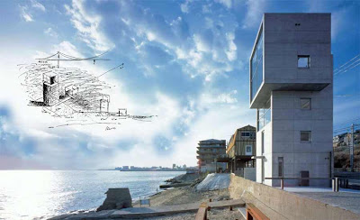
-From the Tado Ando dwgs, create a new AutoCad file with the plans sections and elevations.
-Scale the dwgs so the run of the stair = 1’
-Delete all fills
-Pruge, explode and overkill the dwgs
In Maya
-Import dwgs
-Delete the group “world”
-Center pivot the dwgs at the group level
-Measure to see if the dwgs are to scale
-If the dwgs need to be scaled, scale on the group level by 2.54 on the x,y, and z
-Select each elevation separately and group them (ctrl g) group 1 is east, group2 is north, group 3 is west, and group 4 is south.
-Do the same for the plans and section.
- If the plans, sections and elevations are not in the same scale, you might need to scale the plans and sections so they mach the elevation dwgs (the correct dimensions are approximately 16.76’ across) You may need to scale the plans down to .8
-With the snap to curve on, move the center pivot to the corners of the grouped elevation and Rotate and move each grouped elevation into place, creating a 3d dwg of the house.
-Using separate cubes, build all pieces of the elevations separately, measure the height, width and thickness of each piece and in the channel editor enter the dimensions each cube with the x,y,z scale.
-Using the create polygon tool, trace each floor inside the wall, and around the stair well.
-Measure the thickness (height) of slab in the section dwg, Make new layer called elevations and put all the cubes on the layer.
-Extrude the floor slabs. Make new layer called FL plans and put all the floor plans on the layer.
-Place floor slabs into place in working elevation dwg.
-Use these methods to complete the model.
-For this tutorial to be considered complete, all elevations, floor slabs, stairs, window frames, and outdoor stair and platform need to be modeled.
Tutorial 3


Go to window> settings and preferences> plug-in manager
Load DirectConnect.mll and everything else
Go to file> import> and click on the box
In the import options window, under general options, file type select “best guess”
Click “import” and open the cleaned “plan for maya” AutoCad file
In the options window delete the “world” group.
Select the “RealDWG” group; push the letter ‘f’ button to center the dwg in the perspective window.
Center Pivot
Select the snap to curve, and measure the length of one of the buildings.
If the dwg comes in with the correct scale= good. If it comes in the wrong scale, scale the dwg out by 2.54 (xyz)in the channel editor.
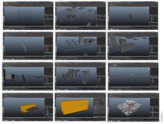
The Buildings and Blocks
Go to the top view and using the create polygon tool, with the snap to curve on, trace all buildings and blocks
Go to the perspective window, and select a flat polygon, goto > edit mesh, make sure “keep faces together” is engaged, and click on the box next to extrude
In the extrude options box, Divisions= 1, smoothing angle= 45, and Offset= 0
Click extrude, and determine the height of the buildings and blocks in the channel editor, “Local Translate Z” (this maybe a negative number if your arrows are in the wrong direction).
The Elevated Train
Go to the top view; go to the surface menu (left side of the screen)
Select two curves to attach, go to edit curves> attach curves and click on the box, in the attach curve options window, attach method= attach, and multiple knots= keep, click attach. Repeat for all rail curves by selecting the curves to attach and pressing the letter “g” button (this only work if you do nothing else in between).
Measure the distance of the rails
Offset the curve ½ the measure distance, go to edit curve> offset > offset curve and click on the box. Active view should be selected, and n the offset curve distance box type in the offset distance.
With your snap to curve on, create a new polygon cube (make sure you reset your one click units)
Scale the cube the width of the rail, and rotate it so it’s parallel to the middle curve.
Move the cube off the curve a couple of inches, right click on the cube and select face option.
Select the face closest to the curve, and hold down shift and select the curve, go to the polygon menu
Go to edit mesh> extrude> click on the box, set the divisions to 100, click on use selected curve for extrusion, taper =1 and twist=0.
Repeat steps for the other rail.
For the train station
Scale out a cube the size of the plan
Center Pivot and duplicate the cube, scale in on z and y and out on x
Boolean the cube, and repeat the Boolean with different cubes to create other holes
Subscribe to:
Comments (Atom)


